BoundarySeer connects Boundary Elements (BEs) into subboundaries only if connections meet certain criteria. For all types of data, BEs must be adjacent to form a subboundary. For numeric raster and point data, gradient angle thresholds are used to evaluate connections further.
Remember that BoundarySeer uses gradient magnitude, the amount of change between samples, for numeric point and raster Boundary Likelihood Values (BLVs). Another crucial component is the direction of that change, its angle, theta, measured between the gradient vector and the X axis.
BoundarySeer evaluates two angles: (1) between for the pair of BEs and (2) between the gradient angle and the connection. Threshold values for these comparisons can be entered in the "Other" tab in the Wombling dialog box. You can access this dialog from the "Data" menu, by first clicking on "Detect Boundary," then "Wombling."
Gradient angle thresholds are applied separately to every variable used in detecting the boundary. Then, BoundarySeer compares the average gradient angle to the threshold. If the average is higher than the threshold, the two BEs being compared will not be connected.
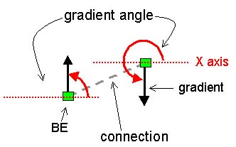
If two gradients have equal magnitude but opposite directions, they do not delineate a consistent area. In the figure below, the gradient at one BE is increasing towards the top of the screen, for the other it is increasing towards the bottom. Although these two BEs have similar gradient magnitude, the direction of change is opposite. To prevent connecting BEs with different directions of change, BoundarySeer compares the two gradient angles. If the angles for the BEs differ by more than a user-set threshold, adjacent BEs are not connected. The example below illustrates two gradients, one with an angle of 90º, the other with an angle of 270º. Their difference is 180º, the maximum possible.
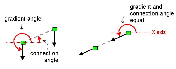
The second gradient angle threshold compares the angle between the gradient and the connection. The gradient angle and the connection angle are measured from the X axis (see figure below). BoundarySeer calculates the difference between the two angles.
The rationale behind this check is to verify the subboundary. Difference boundaries separate dissimilar areas. Thus, connections between BEs should be made across rather than along the direction of change. If the connection is along the gradient, then similar areas will be on either side of the boundary. In essence, the connection links parts of one thick gradient comprising both BEs (see right figure below).
Imagine topographic contours. The contours describe areas of similar elevation above sea level. The direction of topographic change is perpendicular to the contour lines: rain travels down the landscape across contour lines. Even if the hill rises at a steady incline (a uniform magnitude of change or BLV), you would not want to draw a topographic boundary up the surface of a hill. In connecting points up a hill, the boundary would connect BEs of similar gradient magnitude but different elevations. To avoid connecting along a thick gradient, BoundarySeer compares the angles of the gradient with the connection angle.
Default threshold values are set at 90º for the maximum angle between gradient vectors and 30º for the minimum angle between the vector and the boundary. To examine the influence of these values on your boundaries, you might consider testing a range of values and comparing the results. If you would like to set the values so that all adjacent BEs will be connected, choose the values 180º (maximum angle between adjacent gradient vectors) and 0º (minimum angle between vector and connecting line).
Barbujani et al. (1990) connected only those BEs that (1) are adjacent to other BEs and (2) have angles that, for each variable, differ by less than 30° from adjacent boundary elements. They reasoned that if the angles for two adjacent BEs differ by more than 30°, there is a substantial probability that they are not part of the same contiguous boundary.
Next Step:
See also: